Three, four or five axes: the number of axes on a machining center determines which shapes you can produce, how many times a part has to be re-clamped and how you program it. More axes do not always mean better: a more complex machine calls for more programming and more skills. Here is what each configuration brings and how to choose according to your parts.
What is a machining center?
A machining center is a CNC machine tool, usually built on the basis of a milling machine, fitted with an automatic tool changer. It combines milling, drilling and boring to machine a part as completely as possible. Machining centers are classified as vertical or horizontal according to the spindle orientation, and then by number of axes.
3-axis: the basics
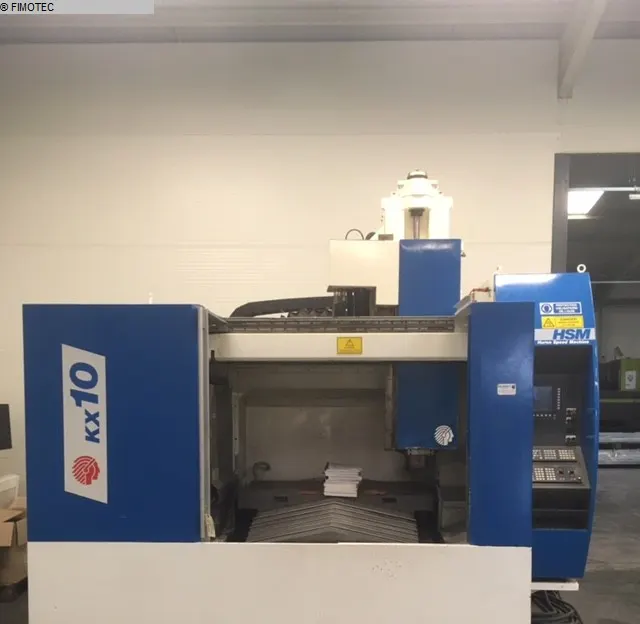
A 3-axis machining center moves the tool relative to the part along three linear axes, X, Y and Z, with the Z axis parallel to the spindle. It is well suited to:
- prismatic parts machined mainly from the top: plates, base plates, housings, pockets;
- drilling and tapping on one face;
- batches where turning the part over between operations is acceptable.
Its limit: every additional face requires a new setup. Each re-clamping takes time and increases the risk of positional error between faces, which is exactly what complete machining on a multi-axis machine aims to avoid.
4th axis: a rotary table
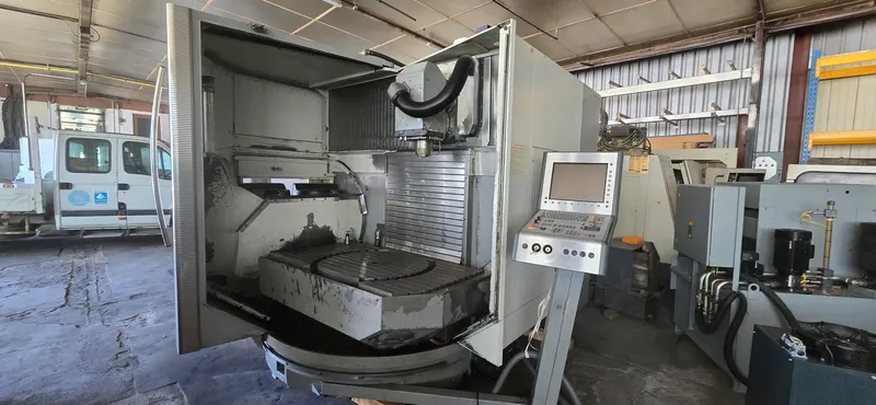
The fourth axis is usually a rotary axis provided by a rotary table mounted on the machine table. On a CNC mill, this table becomes a controlled axis that makes it possible to:
- machine several faces of a part in a single setup;
- drill equally spaced holes on a flange;
- mill helixes or curved contours.
The 4th axis can be used for positioning (rotate, clamp, machine) or continuously, when the control coordinates the rotation with the linear axes. Adding a rotary table to a 3-axis machine requires a control able to drive an extra axis. Several machining centers in Fimotec's stock are listed with a 4th axis on their page, such as the Chiron FZ12 WM.
5-axis: two rotary axes
A 5-axis machine adds two rotary axes to the three linear ones. Each motion is produced either by the table carrying the part or by the tool, so two "5-axis" machines can move in very different ways. There are three main layouts:
- Tilting rotary table (trunnion): the part tilts and rotates while the spindle stays vertical. A vertical spindle combined with a tilting table is a very common machining center layout. The weight and size of the part must suit the table.
- Swivel head: the tool tilts, the head swiveling about two axes; the part stays still, which reduces the loads on the machine with heavy parts.
- Mixed layout: one rotary axis in the head, the other in the table.
3+2 or continuous 5-axis?
CAM software offers several tilt strategies: 3+2, automatic indexing and simultaneous 5-axis machining.
- 3+2 (positional 5-axis): the two rotary axes orient the part or the tool, then stay locked while the three linear axes do the cutting. It is the way to machine several faces and angled holes in a single setup.
- Continuous (simultaneous) 5-axis: all five axes move together. The tool follows the surface at a favorable angle, which allows complex shapes and curved holes, improves surface finish and extends tool life.
A machine capable of simultaneous 5-axis machining can also work in 3+2; the reverse is not true.
Programming and CAM
The more axes, the more central CAM becomes. The software calculates toolpaths from the 3D model, with roughing then finishing passes, and converts them into G-code for the machine. For 5-axis work you also need:
- a post-processor that takes the machine's kinematics into account;
- toolpath simulation and collision checking between tool, holder, part, fixture and machine;
- programmers and operators trained on these machines.
CAM software reduces manual programming work, but it does not replace the know-how of programmers and operators.
Workholding
- 3-axis: vises, clamps and dedicated fixtures; the part is turned over between operations.
- 4-axis: part mounted on the rotary table, with a tailstock for long parts, or a fixture carrying several parts on its faces.
- 5-axis: compact, raised clamping that gives the tool access to the faces; the goal is to machine as many faces as possible in one clamping, with less handling and fewer re-clamping errors.
Part examples
- 3-axis: plates, base plates, housings, pockets and holes on one face.
- 4-axis: flanges with spaced holes, cylindrical parts, prismatic parts machined on several side faces.
- 5-axis: aircraft parts, engine housings, medical implants, impellers, turbine blades, tire molds.
How to choose
- Your parts: geometry, number of faces to machine, positional tolerances between faces.
- Your volumes: varied small batches or repeat production.
- Your programming resources: CAM software, post-processor, 5-axis skills.
- Part size and weight, compared with the machine's table and travels.
- The overall investment: a multi-axis machine is more complex and more expensive than a 3-axis one, and CAM, training and workholding come on top.
For many shops, a 3-axis machining center with a 4th axis, or a 5-axis machine used mostly in 3+2, can be a good compromise.
Machining centers at Fimotec
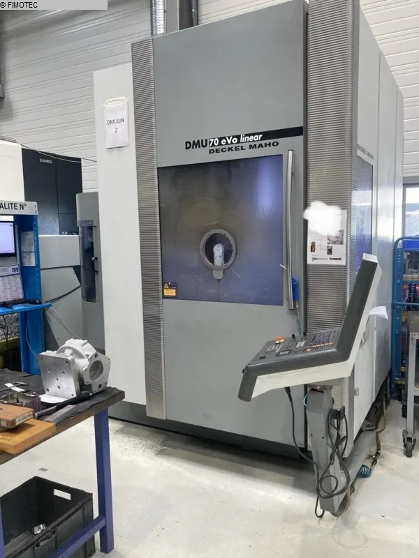
Fimotec's stock in Haguenau includes 3-, 4- and 5-axis machining centers from several makers, including Deckel Maho. The Deckel Maho DMU 100T, for example, is listed with 5 axes. Each machine page lists the specifications recorded on the machine and, when available, the manufacturer's data, together with a tier; the price is given on request. If the configuration you need is not in stock, Fimotec can search for a machine on request: write to us and you will get an answer within 48 working hours.