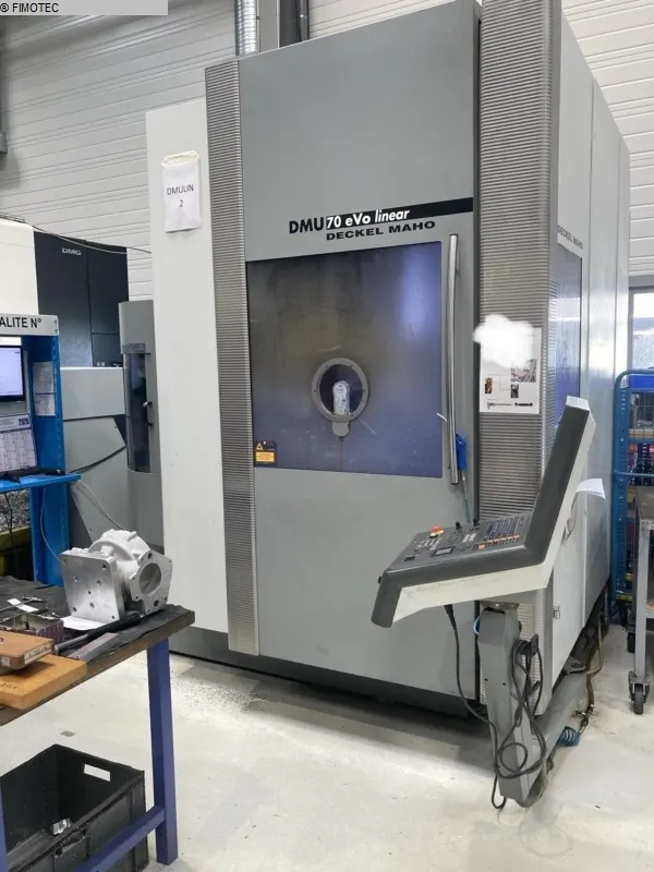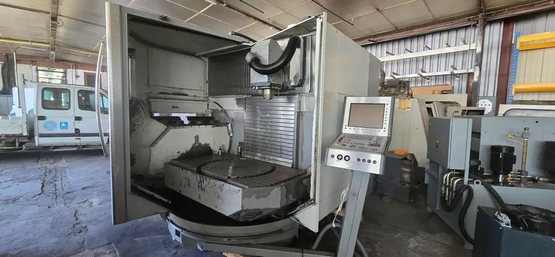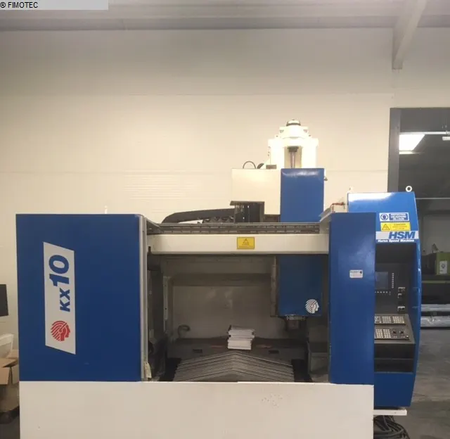
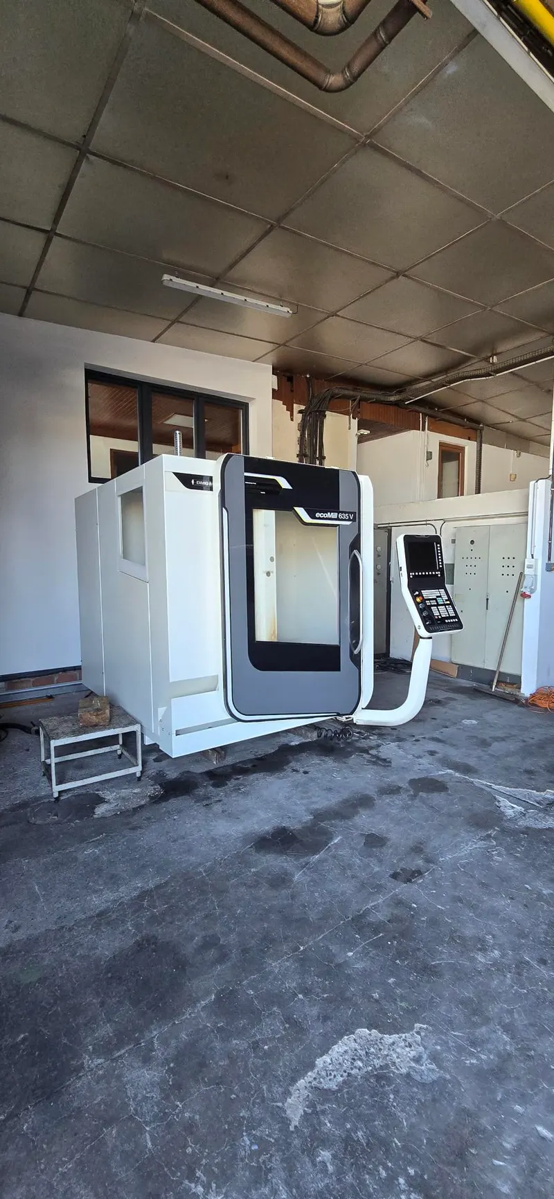
A specification sheet sums up in a few lines what a machine can do: part size, speeds, forces, tooling. Reading it properly avoids finding out too late that a part does not fit between the columns or that the spindle lacks torque for a large-diameter cutter. Here is what the most common specifications cover, and how to compare two machines without being misled by figures that do not measure the same thing.
X, Y and Z travels
Travels give the maximum movement of each linear axis, in millimetres. They define the area the tool can reach, but they do not directly give the maximum part size. You have to subtract the room taken by the fixturing, allow for tool length and, for the vertical axis, for the distance between the spindle nose and the table. On a machine with columns, the distance between columns also limits part width.
The table: size and permissible load
The table size shows the room available for clamping parts and fixtures. The permissible load is the maximum mass that can be placed on it: it includes the part, but also the vice, the fixture or the indexing table. For heavy parts, this value often decides between two machines with similar travels.
The spindle: taper, speed, power and torque
The spindle taper (SK 40, BT 40, HSK-A63…) determines which toolholders can be used: check this before any purchase if you already own a stock of toolholders.
Maximum speed, in revolutions per minute, matters for small tools and soft materials. Power and torque matter for heavy stock removal. The two are linked: power is torque multiplied by angular speed. At equal power, the available torque therefore falls as speed rises. A high-speed spindle and a high-torque spindle do not meet the same need, and a maximum power figure alone says nothing about the torque available at low speed. If a sheet gives several power or torque values, check which operating mode each one refers to, and compare like with like.
The magazine and tool change
A machining center is defined by its automatic tool changer, which takes tools from a magazine and places them in the spindle. On the sheet, look at:
- the number of magazine pockets;
- the maximum diameter, length and weight of the tools accepted;
- the tool change time.
For the latter, two measures are in use. The tool change time alone, and the "chip-to-chip" time, defined by guideline VDI 2852 as the time between the moment one tool leaves a machining position and the moment the next tool reaches it. On recent machining centers, these times sometimes go below three seconds. Always compare the same measure.
Feeds and rapid traverses
Rapid traverse is the positioning movement of the slides when the tool is not cutting; as soon as the tool is working, it is called feed. Rapid traverse rates generally range from about 6 to 100 m/min depending on the machine. They cut idle time, especially on parts with many short operations, but they require a machine able to absorb the accelerations. The maximum cutting feed depends mainly on the tool and the material. Watch the units: some sheets give mm/min, others m/min.
Lathes: swing, turning length, bar capacity
On a lathe, three values describe the working space:
- the swing over the bed, which is twice the centre height;
- the swing over the cross slide, often much smaller;
- the turning length, or distance between centres.
The swing over the bed is not the maximum part diameter: the chuck jaws have to rotate too, and the carriage must be able to pass under the part for rigid external turning. In practice, a few millimetres often decide whether a part fits or not. A lathe spindle is often hollow, which allows bar stock to be fed to the chuck: the bar capacity gives the bar diameter that can pass through it, a key figure when working with a bar feeder.
Grinding machines: grinding capacity
On a surface grinder, the part, often held by a magnetic chuck, moves on a table under the wheel: capacity is read as grindable length, width and height. On a cylindrical grinder, the part rotates in front of the wheel, for example between centres: look at the grinding diameter and the distance between centres. Wheel dimensions and wheel spindle power complete the sheet.
Footprint, weight and supply
Overall dimensions and weight are used to plan transport, handling and installation. Check whether the dimensions include the chip conveyor, the electrical cabinet and the door opening. The power supply (voltage, connected load) and, where applicable, compressed air must be checked against your workshop.
Recorded on the machine or manufacturer's data?
A value recorded on a machine describes that very machine, with its options and any modifications. The manufacturer's data describe the model as it was offered, sometimes with options the machine does not have. On the Fimotec website, each machine page shows the specifications recorded on the machine and, when they exist, the manufacturer's data, each with its origin: "Recorded on the machine" or "Manufacturer's data", with a link to the source document. If a value that matters for your project is missing or differs between the two, ask: every request gets an answer within 48 working hours. To discuss it, contact Fimotec.
Comparing two machines
- Start from your parts: dimensions, weight, material, tolerances and quantities.
- Compare like with like: same unit, same definition of tool change time, same operating mode for power.
- Tell standard equipment from options.
- Check tooling compatibility: spindle taper and the toolholders you already own.